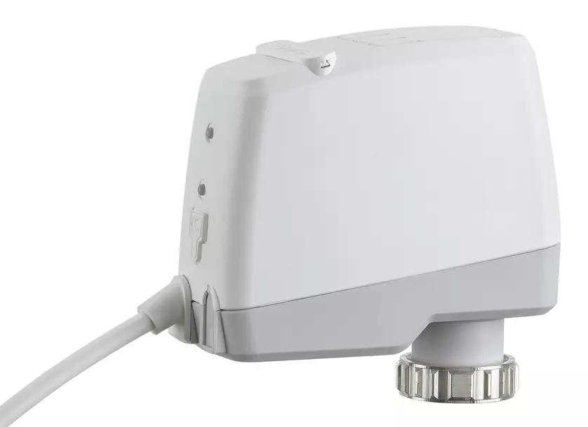
TA-Slider 160 Fail-safe
Digitally configurable proportional push actuator with electronic fail-safe function – 160/200 N
Digitally configurable fail-safe actuators with or without change-over, and a wide range of setup options provide extensive flexibility for on-site parameter adaptation. Fully programmable binary input, relay and adjustable max. stroke of the valve bring new opportunities for advanced hydronic control and balancing.
Product branding

Features and Benefits
Fully configurable fail-safe
Setting of stroke position (extended, retracted or intermediate position) and delay feature for entering/leaving fail-safe mode for a reliable and optimal fail-safe function.
Convenient, reliable setup
Fully customisable by smartphone via Bluetooth using a TA-Dongle.
Fully configurable
More than 200 setup options allow input and output signals, binary input, relay, characteristics and many other parameters to be configured.
Easy diagnostics
Tracks the last 10 errors to allow system faults to be found quickly and health check of fail-safe function.
Quick copying of settings
Setup configuration can be copied quickly from the TA-Dongle to identical TA-Slider actuators.
Functions
Delayed start-up
Diagnostic/Logging
Electronic fail-safe function
Manual override (TA-Dongle)
Minimum stroke setting
Mode, status and position indication
Proportional control
Self-adjusting force
Stroke detection
Stroke limitation setting
Valve blockage protection
Valve clogging detection
Temperature
Max. medium temperature: 120°C
Operating environment: 0°C – +50°C (5-95%RH, non-condensing)
Storage environment: -20°C – +50°C (5-95%RH, non-condensing)
Control speed
10 s/mm
Supply voltage [V]
24 VAC/VDC ±15%. Frequency 50/60 Hz ±3 Hz
Power consumption
Peak: < 6.6 VA (VAC); < 3.2 W (VDC)
Operation: < 2.0 VA (VAC); < 0.9 W (VDC)
Standby: < 1.4 VA (VAC); < 0.45 W (VDC)
Peak consumption occurs for a short period after a power cut for recharging capacitors.
Input signal
0(2)-10 VDC, Ri 47 kΩ.
0.33 Hz low pass filter.
Adjustable hysteresis sensitivity 0.1-0.5 VDC.
Default setting: Proportional 0-10 VDC
Proportional: 0-10, 10-0, 2-10 or 10-2 VDC.
Proportional dual-range (for change-over): 0-3.3 / 6.7-10 VDC, 2-4.7 / 7.3-10 VDC, 0-4.5 / 5.5-10 VDC or 2-5.5 / 6.5-10 VDC.
Proportional split-range: 0-5, 5-0, 5-10 or 10-5 VDC; 0-4.5, 4.5-0, 5.5-10 or 10-5.5 VDC; 2-6, 6-2, 6-10 or 10-6 VDC.
Output signal
0(2)-10 VDC, max. 8 mA, min. 1.25 kΩ.
Default setting: Proportional 0-10 VDC
Ranges: See “Input signal”.
Stroke
6,9 mm
Automatic detection of the valve lift (stroke detection)
Noise level
Max. 30 dBA
Marking
Label: IMI TA, CE, product name, article No. and technical specification.
Colour
White RAL 9016, grey RAL 7047.
Adjusting force
160/200 N
Self-adjusting for IMI valves.
Connection to valve
Swivelling nut M30x1,5
Cable
1, 2 or 5 m.
Halogen free with wire end sleeves.
Fire class B2ca – s1a, d1, a1 according to EN 50575.
Type LiYY, 5x0.25 mm2.
Relay cable (R24 version):
1, 2 or 5 m.
Halogen free with wire end sleeves.
Fire class B2ca – s1a, d1, a1 according to EN 50575.
Type LiYY, 3x0.34 mm2.
Material
Cover: PC/ABS GF8
Housing: PA GF40.
Swivelling nut: Nickel-plated brass.
Ingress protection
IP54 all directions (according to EN 60529)
Protection class
III (SELV)
(according to EN 61140)
Certifications and directives
EMC-D. 2014/30/EU: EN 60730-1, -2-14.
LV-D. 2014/35/EU: EN 60730-1, -2-14.
RoHS-D. 2011/65/EU: EN 63000
The table below assists you in finding the relevant product based on its variant. For more details, please download the datasheet above.
| Art. No. |
|---|

